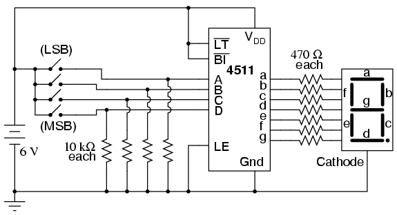


If you haven't already installed the latest USB driver, SimpleIDE, or Learn folder, go to Propeller C - Set up SimpleIDE and Propeller C - Start Simple. The test code will count from 0 to 9 on the display, with half a second between each digit. You will need to adjust your pin assignments in the code if using the FLiP. Note: The FLiP wiring diagram uses pins 6-13, not pins 8-15. Build the circuit for the FLiP using the diagram below:.Build the circuit for Activity Board using the diagram/schematic below (the images show 100 ohm resistors, but use 1k ohm resistors instead):.Or, you can substitute 220 Ω resistors (red-red-brown) if necessary. It’s best to use resistors of the same value so all the segments light up evenly. Any resistor value between 100 Ω and 1 kΩ will work for the LED resistor and the lower the resistance, the brighter the segment. When each I/O pin is set to high (outputs 3.3 V), the LED it is connected to lights up. This tutorial will show you exactly how to control the display, and use it to count.Įach individual LED in the 7-segment display needs a resistor between it and the Propeller’s I/O pin. This display uses seven LEDs arranged in a special pattern that makes it possible to show any number from 0 to 9. You can find these in many products that need to display numbers in a simple way, like clocks, kitchen appliances, or digital scales. A 7-segment display is a great way to display numbers using your Propeller.


 0 kommentar(er)
